Breezair Evaporative Cooler Troubleshooting and Diagnostic Guide
| Make/Model | Serial # | Date |
| Breezair – Direct Drive Models (ICON series) | N/A | 25/09/2024 |
| Preface |
This document assumes you have a basic level of electrical competence, own a suitable multimeter and know how to use it.
Some procedures in this document are potentially dangerous if not followed correctly and with due care. High voltages can be present, which could result in an electric shock, electrocution or damage to test equipment.
| Safety Warning |
High voltages, up to approximately 420V DC are present inside the control module during normal operation. This energy can be stored in the control module even after the mains power has been turned off. Under some fault conditions, this voltage may be present at the 3-pin motor power connector. This could result in an electric shock, electrocution or damage to your multimeter.
| Equipment |
Suggested Equipment:
-
Multimeter with Diode Test Mode (
 )
) -
Medium Flat Screwdriver
Some tests can be performed without the use of a multimeter.
Use the flat-head screw driver to aid in removing the pad frame clips to gain access to the inside of the evaporative cooler.
| Preliminary Control Module & Communication Test |
Turn on the cooler at the wall control/remote control and put the cooler into Manual and COOL modes (press the AUTO or MODE button to change to Manual mode, then press the COOL or COOL/VENT button to change to COOL mode).
Wait 10 minutes and then turn off the cooler. If you find that the pads are dry or that there’s no water in the sump at the bottom of the cooler, then you may have a communication problem, faulty solenoid valve or faulty salinity probes.
If you did the above test and found that the pads are now wet, the next test to do is to turn on the cooler and put it in VENT, Manual mode. Leave the cooler on and check if the “POWER” LED on the front of the control module is illuminated. If the “POWER” LED is not illuminated, then the control module has failed. Please contact us if you’d like to have your control module repaired.
| Motor Output Stage Test |
Turn off the control module, using the isolation switch on the front of the module. Wait 30 minutes before proceeding with the following test. If you do not wait long enough, your test results will be invalid, as if there is a charge stored inside the control module, it will interfere with the tests described below.
The following set of tests allow you to check the motor power output circuitry within the control module for internal short circuits. This is one of the common failure modes of the control module. If any fault is found while doing these tests, the motor will also need to be checked for short circuits in the windings.
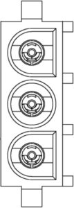
With the multimeter set to diode (![]() ) test mode, place the positive (+) and negative (-) multimeter probes at the locations shown in the illustration below. Wait for the reading on the multimeter to stabilise before moving on to the next test. It will usually take 5-10 seconds for the first test reading to stabilise.
) test mode, place the positive (+) and negative (-) multimeter probes at the locations shown in the illustration below. Wait for the reading on the multimeter to stabilise before moving on to the next test. It will usually take 5-10 seconds for the first test reading to stabilise.
The following tests should all read as “OL” (over-limit) on the multimeter. Readings of low values indicate an internal short circuit in the motor output circuitry within the control module.
If you believe you have a faulty control module, please contact us to discuss having it repaired.
|
|
TEST 1 | TEST 2 | TEST 3 | TEST 4 | TEST 5 | TEST 6 |
+ |
+ |
– |
– |
|||
– |
+ |
+ |
– |
|||
– |
– |
+ |
+ |
|||
| Direct Drive Motor Tests |
The direct drive motors in the Breezair evaporative coolers have been known to develop short circuits in the windings. This is particularly the case with the older green coloured motors.
When short circuits occur in the motor windings, it can also damage the control module.
There are two methods described below to test the motor for short circuits within the windings. There’s no need to do both tests, however the resistance test is recommended.
| Motor Test 1: The Flick Test |
This test does not require any test equipment.
-
Turn off the power to the control module, using the isolation switch on the front of the control module.
-
Wait until all LEDs on the front of the control module have turned off.
-
Disconnect the motor power cable from the control module. This is the round cable that plugs into the second connector from the left at the bottom of the control module.
-
Remove one of the cooling pads to get access to the fan blades.
-
Give the fan a modest flick.
You should get approximately 1-1.5 revolutions out of the fan fairly easily. If there’s a short circuit in the windings, the motor will stop very quickly, usually within ½ a revolution. The fan motor should spin freely, but will feel heavy. You can confirm whether or not you have a short circuit in the motor windings by checking the winding resistance, as described below:
| Motor Test 2: Check Winding Resistance |
This test requires a multimeter.
-
Turn off the power to the control module, using the isolation switch on the front of the module.
-
Wait until all LEDs on the front of the control module have turned off.
-
Disconnect the motor power cable from the control module. This is the round cable that plugs into the second connector from the left at the bottom of the control module.
-
Using a multimeter, measure the resistance between pins 1-2, 2-3 and 1-3 at the plug on the end of the motor power cable.
The resistance between all pins should be about the same and within the range of 15 – 25 ohms. Lower values, such as 2.5 ohms, would indicate a short in the motor windings. This would mean that the motor needs to be replaced.
| Water Solenoid Valve Test |
When the cooler is turned on and set to COOL mode, the control module should close the drain valve and then supply approximately 24V AC to the solenoid valve, causing it to open and allow water to fill the tank. There is a small delay of around 15 seconds to allow the drain valve to close before power is sent to the solenoid valve.
By default, the cooler will wait 8 minutes for water to be detected at the salinity probes, before shutting down. As such, if testing takes longer than 8 minutes, you will need to turn off the cooler and re-start it on COOL mode before continuing.
In some cases, the solenoid valve may only open for approximately 10 seconds, and then shut off. If this happens, it is usually due to a fault within the control module.
The solenoid valve can become stuck in either the open or closed state or not open fully. It is common for the valve to become stuck closed, in which case no water can enter the cooler. If the water flow is restricted, this is usually due to the solenoid valve only opening partially, which requires that the solenoid valve be replaced. The solenoid valve is supposed to open fully and allow the cooler to fill up quickly.
To determine if the solenoid valve is faulty, first ensure that the cooler has been drained of all water. You can do this by pressing the DRAIN button on the wireless remote, or by turning off the cooler on the hard-wired remote and the pressing and holding the “UP” and “DOWN” buttons together, until dr starts flashing on the display. Alternatively, you can turn off the power to the cooler for 10 seconds, then turn it back on, and the cooler should drain (when operating on default settings).
Once the water has been drained, turn on the cooler and put it into Manual and COOL mode. After approximately 15 seconds, the solenoid valve should be energised and water should flow into the cooler. The cooler will generally fill most of the way within 30-45 seconds. If the cooler takes a long time to fill, the solenoid valve is probably faulty.
If no water enters the cooler, then using a multimeter and with the cooler still turned on, check that there is 24V AC present at the solenoid valve terminals. If 24V AC is present, but no water is flowing into the cooler, then the water supply to the cooler may be turned off or the solenoid valve may have failed.
To determine if the solenoid valve has gone open-circuit (burnt out), disconnect the wires from the solenoid valve and measure the resistance between the two terminals on the solenoid valve. You should see approximately 40 ohms.
If 24V AC is not present at the solenoid valve terminals, disconnect the solenoid cable from the control module and check if there is 24V AC present at the solenoid valve connector on the control module. If there is 24V AC present, then the cable going to the solenoid valve should be repaired or replaced. If 24V AC is not present, then the control module is likely faulty, though this fault is rare.
| Salinity Probe Test |
The salinity probes are used to sense the presence of water in the cooler as well as how electrically conductive the water is. The cooler will not start the pump unless water is detected by the salinity probes.
When there is no water in the cooler, the “SAL” LED should be solid red.
When the cooler is full of water, the “SAL” LED should blink red once every 5 seconds.
If the cooler is full of water, but the “SAL” LED is solid red, then the salinity probes are faulty or that the salinity sensing circuitry inside the control module has failed.
There are currently two different versions of the salinity probes.
Test the 2-prong version by ensuring that the black and blue wires each have continuity to one of the metal contacts on the bottom of the probe assembly. Resistance would normally be less than 1 ohm. The brown wire is not used and can be ignored.
Test the 3-prong version by ensuring that there is continuity from each wire in the cable to one of the metal contacts on the bottom of the probe assembly.
| Drain Valve |
The most common problem with the drain valves is that the bucket inside the drain valve assembly continually moves up and down, rather than either staying in the up position (open) or down position (closed).
If the drain valve exhibits this behaviour, firstly turn off the power to the cooler and then check that there is no debris caught in the bottom of the drain valve, such as leaves, small sticks, rocks, or other objects. If debris is found, remove it and see if this cures the problem.
Check that the rubber bucket washer is still soft, and has not gone hard or brittle. If the washer is hard or brittle, it will need to be replaced. Also check that dirt or other debris has not built up on the bottom of the bucket washer.
You can also try applying a small amount of grease (eg. water-proof grease/tap lubricant) to the outside of the small plastic shaft that protrudes out of the bottom of the drain valve assembly when it is in the closed position.
If none of this helps, the drain valve may need to be repaired or replaced. As the drain valves are expensive, it can be worth purchasing a kit to recondition the drain valve, however, in most cases, all you will usually require is a replacement motor for the drain valve and possibly a new bucket washer (the large washer on the bottom of the bucket inside the drain valve assembly). There are also two micro-switches/limit switches inside the drain valve assembly, but these don’t usually fail.
We can currently supply replacement motors and bucket washers for the 24V AC drain valves used in the Breezair, Braemar and Coolair evaporative coolers. In late 2024, we will be supplying kits to recondition the drain valves at a reasonable price. Please contact us for a quote.
When the drain valve begins to fail, you will usually see the bucket inside the drain valve trying to move down (into the closed position), and then contacting the bottom of the drain valve assembly and coming back up again, into the open position. This cycle may repeat a few times or go on indefinitely.
When the motor inside the drain valve assembly develops a mechanical issue, it can automatically reverse direction, which is what usually causes the drain valve to open and close repeatedly. It is almost never a fault in the electronics inside the control module.
The motor has a bushing around the output shaft, which can collect dust and other grime over time, causing the output shaft to seize up inside the bushing. At this point, the motor may stop working entirely, or the bushing may begin to rotate, which it is not supposed to do. If this happens, the motor can become overloaded, causing the motor to automatically reverse direction, which in turn causes the drain valve bucket to return to the up/open position. This is usually observable when the drain valve is closing and the bucket washer has just made contact with the bottom of the drain valve, as the motor is under the most stress at this point.
If you are in need of cooling and this problem is occurring, you can wait for the drain valve to close and then disconnect the drain valve cable from the control module. This will leave the valve in the closed position and the cooler will be able to fill with water. Note that this will cause a code 4 fault when the control electronics eventually attempt to drain the cooler, but this can be ignored. The cooler will also need to be drained periodically, so that the water is kept fresh and doesn’t cause excessive mineral buildup on the cooling pads. Note, however, that if your cooler is under warranty, doing this will likely void your warranty if discovered by a service technician.
| Pump |
By default (standard cooler configuration), the pump will only start once the control module senses that water has been present at the salinity probes for approximately 30 seconds. If the control module is unable to sense the presence of water at the salinity probes, either due to faulty salinity probes or a fault in the salinity sensing circuitry inside the control module, the pump will not start.
To check that the coil inside the pump has not burnt out or otherwise gone open-circuit, firstly take note of the orientation of the pump power connector while it’s plugged into the control module, then disconnect the pump from the control module and measure the resistance between the top two pins of the connector on the pump power cord. The pump should measure approximately 120 ohms, and there should be no continuity between the top two pins and the bottom pin.
Under normal circumstances, the pump will run for 4 minutes to pre-wet the pads before the fan is started.
| Fault Codes (EXH/EZH Series) |
Breezair Fault Codes:
| Code | Fault Description |
| 01 | Communications problem. Check the communication cable between wall control and cooler for damage. Note: You can use a curly cord from an old telephone handset to connect the wall control to the cooler for testing purposes (eg. Jaycar Electronics P/N: YT6047 or Altronics P/N: P7078). |
| 02 | Water not detected at the salinity probes. The water supply to the cooler may be turned off, the solenoid valve may be stuck closed and not allowing water into the cooler, the salinity probes may be faulty, the drain valve may be stuck open or not closing (cycling open/closed), or the control module salinity sensing circuitry may be faulty. If you receive fault code 2 within 10-15 seconds of turning the cooler on, then the control module is faulty. |
| 03 | EEPROM failure. The control module stores a small amount of data related to settings for the operation of the cooler. If this data becomes corrupt, you will often receive fault code 3. The control module will need to be repaired. |
| 04 | The cooler has failed to drain the water from the tank/sump. After waiting 4 minutes for the water to drain, water was still detected by the salinity probes. This suggests either a faulty drain valve (not opening) or a blockage in the drain pipe. |
| 05 | Not Documented / Probably Unused. |
| 06 | Not Documented / Probably Unused. |
| 07 | Mains power supply frequency is incorrect. In Australia, we have a nominal 50Hz power supply frequency. Fault code 7 will be produced if the mains frequency is outside the limits of 46-54Hz. This can be caused by contamination to the circuit board inside the control module (eg. spiders and other insects), generators, a loose/bad connection at the power entry connector or other internal faults. Electrical arcing on the cooler circuit in the premises may generate this fault as well. |
| 08 | A brief power failure has been detected. This fault isn’t displayed as a service code but it’s stored in the fault log inside the control module. It isn’t anything to worry about in general. |
If you have a wireless remote control, you will not receive fault codes from the cooler, however you can still determine if a fault code is being reported by looking at the “DIAG” LED on the front of the control module inside the cooler. The “DIAG” LED will turn red and flash a number of times with a longer pause between the sequence of flashes. Count the number of flashes between the longer pauses to determine the fault code.
The “DIAG” LED indicates normal operation by continuously flashing two green flashes between a longer pause. Do not mistake this for fault code 2. As mentioned above, the “DIAG” LED will flash red when it is flashing a fault code.
The “DIAG” LED can also be used to determine if the cooler is receiving commands from the remote. The “DIAG” LED will flash a long solid green or amber flash when it receives a command from the remote.
A long green flash means that the command has been received and the cooler should act on the command.
A long amber flash means that the cooler received a command, but that the transmission code sent from the remote doesn’t match the code stored in the control module. Usually the remote needs to be paired with the cooler again in this case. Send us an e-mail or give us a call and we’ll walk you through the pairing procedure at no charge.
If you find that pressing buttons on the remote doesn’t result in any change at the “DIAG” LED, then nothing was received by the cooler. This tends to be a control module fault but can also be caused by damage to the wiring going to the receiver module or a damaged receiver module. The remote controls don’t generally develop faults in the transmission circuitry, but can develop faults that cause the transmission code to change at random. Receiver modules can go “deaf” and in some cases, if you hold the receiver to the back of the remote control and then turn on the cooler with the remote, the cooler may operate. In this case the receiver generally needs to be repaired or replaced, but try replacing the batteries in the remote control first.
All troubleshooting should be done with the remote/wall control in MANUAL mode.
Note that there aren’t any fault codes for the fan, as there is no way for the fan circuitry to communicate faults other than by flashing LEDs on the front of the control module. A common fault of these control modules is that everything works except the fan. To determine if it’s a control module fault, put the cooler into MANUAL and VENT modes and then check if the “POWER” LED on the front of the control module is illuminated. If it’s not, then the control module has failed and will need to be repaired or replaced. If you hear the fan motor buzz, groan or occasionally make a clunking noise while the fan is running (one initial “clunk” at startup is normal, but repeated random clunking is not), turn off the cooler immediately and call us, as this is often a sign of a short circuit in the fan motor windings or a damaged inverter module inside the control module assembly. Continued attempts to run the fan will usually render the control module irreparable.
SAL (Salinity LED) Fault Codes and Status Information (EXH/EZH Models):
| Flashes | Fault / Status Description |
| OFF | Salinity circuit disabled (bleed tray mode). This mode is used when the cooler is set up to permanently hold water and periodically drip water to keep the water from becoming too saline. |
| 1 | Normal Operation. Water has been detected at the probes and the salinity is within the set limits. The salinity circuitry will monitor the water salinity and drain water when necessary to freshen up the water. |
| 2 | Salinity above the set point. The cooler will drain some water and re-fill shortly. |
| 3 | Salinity control is set for timed drain. The cooler will periodically drain water to keep it fresh rather than using the salinity probes to determine if the water should be refreshed. |
| 4 | Incorrect salinity control method selected (invalid salinity configuration). Call us and we will help you correct the problem at no charge. |
| ON (Solid) |
No water present or unable to detect the presence of water. When the cooler is in vent mode (fresh air, no cooling) this is normal. When the cooler is in cool mode, the inlet solenoid valve (if fitted) should open and fill the base of the cooler (the tank) with water. If the solenoid fails to open, the SAL LED will be on solid and you will eventually receive fault code 2 or the DIAG LED will turn red and flash a 2 flash sequence repeatedly. |
Troubleshooting Guide Download:
Breezair DD CTRL & Motor Test Procedures.pdf
| Fault Codes (EXQ/EZQ/EXS Series) |
Breezair Fault Codes:
| Code | Fault Description |
| 01 | Communications problem. Check the communication cable between the wall control and cooler for damage. |
| 02 | Water not detected at the salinity probes. The water supply to the cooler may be turned off, the solenoid valve may be stuck closed and not allowing water into the cooler, the salinity probes may be faulty, the drain valve may be stuck open or not closing (cycling open/closed), or the control module salinity sensing circuitry may be faulty. If you receive fault code 2 within 10-15 seconds of turning the cooler on, then the control module is faulty. |
| 03 | EEPROM failure. The control module stores a small amount of data related to settings for the operation of the cooler. If this data becomes corrupt, you will often receive fault code 3. The control module will need to be repaired. |
| 04 | The cooler has failed to drain the water from the tank/sump. After waiting 4 minutes for the water to drain, water was still detected by the salinity probes. This suggests either a faulty drain valve (not opening) or a blockage in the drain pipe. |
| 05 | Not Documented / Probably Unused. |
| 06 | Not Documented / Probably Unused. |
| 07 | Mains power supply frequency is incorrect. In Australia, we have a nominal 50Hz power supply frequency. Fault code 7 will be produced if the mains frequency is outside the limits of 46-54Hz. This can be caused by contamination to the circuit board inside the control module (eg. spiders and other insects), generators, a loose/bad connection at the power entry connector or other internal faults. Electrical arcing on the cooler circuit in the premises may generate this fault as well. |
| 09 | A brief power failure has been detected. This fault isn’t displayed as a service code but it’s stored in the fault log inside the control module. It isn’t anything to worry about in general. |
You can determine if a fault is being reported as the wall control (thermostat) should report this when the cooler shuts down due to a fault. While on the roof, you can still determine if a fault code is being reported by looking at the “DIAG” LED on the front of the control module inside the cooler. The “DIAG” LED will turn red and flash a number of times with a longer pause between the sequence of flashes. Count the number of flashes between the longer pauses to determine the fault code.
The “DIAG” LED indicates normal operation by continuously flashing two green flashes between a longer pause. Do not mistake this for fault code 2. As mentioned above, the “DIAG” LED will flash red when it is flashing a fault code.
A long green flash means that the command has been received and the cooler should act on the command.
All troubleshooting should be done with the wall control in MANUAL mode.
Note that there aren’t any fault codes for the fan, as there is no way for the fan circuitry to communicate faults other than by flashing LEDs on the front of the control module. A common fault of these control modules is that everything works except the fan. To determine if it’s a control module fault, put the cooler into MANUAL and VENT modes and then check if the “POWER” LED on the front of the control module is illuminated. If it’s not, then the control module has failed and will need to be repaired or replaced. If you hear the fan motor buzz, groan or occasionally make a clunking noise while the fan is running (one initial “clunk” at startup is normal, but repeated random clunking is not), turn off the cooler immediately and call us, as this is often a sign of a short circuit in the fan motor windings or a damaged inverter module inside the control module assembly. Continued attempts to run the fan will usually render the control module irreparable.
SAL (Salinity LED) Fault Codes and Status Information – MagIQtouch Models:
| Flashes | Fault / Status Description |
| 1 | Normal Operation. Water has been detected at the probes and the salinity is within the set limits. |
| 2 | Salinity above the set point. The cooler will drain some water and re-fill shortly. |
| 3 | Salinity control is set for timed drain. The cooler will periodically drain water to keep it fresh rather than using the salinity probes to determine if the water should be refreshed. |
| 4 | Operating without a drain valve (aka. bleed tray mode). This mode is used when the cooler is set up to permanently hold water and periodically drip water to keep the water from becoming too saline. |
| 5 | Thermostatic control operation (no water). |
| ON (Solid) |
No water present or unable to detect the presence of water. |